

maxpower
-
Posts
1341 -
Joined
-
Last visited
Content Type
Profiles
Forums
Downloads
Posts posted by maxpower
-
-
Electronic circuits are not always tolerant to continuous brownouts Chinese or otherwise. One should also consider adding transient suppression to devices connected across solar panels.
-
3 hours ago, Tronx said:
Crossy's balancer seems to be his only protection against over-discharge and over-charge. I agree that this is only a balancer, but it has features for battery protection.
I believe Crossy has added proper charge control to his BMS + battery pack and can now charge on the chargers limit instead of the BMS safety limit. If the pack is holding balance and the charger set correctly, for most of the time charging will stop before any BMS safety limit is reached.
He appears to have left the discharge point up to the BMS and although not recommended probably avoids reaching this often because of excess capacity in the pack.
There appears to some mix up between BMS and charge controller. To avoid confusion in the charging process the BMS and charge controller should be considered separately.
-
 2
2
-
-
On 5/19/2021 at 10:21 PM, Tronx said:
Well, we are talking about hobby stuff. These exotic chinese controllers are for the Chinese and their cheap electronics products. No support, no community, in the best case a chinese data sheet.
Which for some hobbyists includes using well documented cheap Chinese microcontrollers.
On 5/19/2021 at 10:21 PM, Tronx said:And even they do not use controllers, but they build little comparator type chips like on the balancer/charge controller shown by crossy. It's only a shame that they are not configurable like stuff from Texas Instruments.
Companies like BYD Hycon HM-Semi manufacture charge control devices with a wide range of pre set parameters and tolerance. The aim is to keep external component count to a minimum and limit production line testing.
Those wanting fully adjustable BMS systems or devices should go out of the bargain basement and up to the next floor.
On 5/19/2021 at 10:21 PM, Tronx said:You cannot set a lower full charge voltage, nor a higher low voltage cut off (or it is not documented). I can upload the data sheets if anyone is interested. Their chips protect the batteries to some extend, but always too close to the edge, reducing life time.
BMS of the type shown are safety protection devices not continuous charge limit controllers. Those with balance features offer a method to dump cell excess at a set voltage. The balance process revolves around charge controller voltage and the point where absorption is low.
Reminder
This topic is about converting existing 220V LED lights to solar. Its an idea that on paper looks simple but in practice not always easy to find an efficient reliable solution.
This is why we often find a set of reasonably well matched components and a simple control processor inside cheap Chinese solar lights.
Back to the hobby market ..
-
1
-
-
1 hour ago, Tronx said:
Your second statement about the microcontroller does not hold in may 2021 anymore. Prices have skyrocketed. An attiny13 costs now over 70 cents. Tiny45 over 1€. These prices will trigger fakes to be produced and sold on Aliexpress.
Now that's funny!
Last time I looked we were down to 4 Cents for 6 legs 8-Bit 16MHz at our local Shenzhen market.
Back to the hobby market...
Battery + panel voltage monitoring and direct FET drive on a $1:20 device that for most of the time consumes less than 1mA, and there's even space left over for a PWM charge controller. It's a no brainer even for a novice Arduino hobbyist.
Anyway just a suggestion for the more daring, now back to the world of open collectors and stuff.
-
6 hours ago, Crossy said:
Current draw with an LM358 is about 1mA at 12V supply to just under 2mA with the lights on (most of the extra is lighting the LED). Not sure if it's really worth going to an ultra low-power device.
Voltage comparison jobs like this are best served by a dedicated comparator like the LM393 with unused input pins of a dual device tied to ground.
Only one mosfet is required (the status led is wasting energy). Voltage can be applied directly through the 100R charge limit resistor, without the 10k.
For anyone with experience, cheap microcontrollers which spend most of the time sleeping are the best choice for these tasks. -
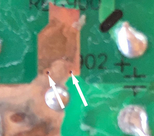
The small holes in the PCB tracks (see photo) are called vias and pass connection from one board side or layer to another. Corrosion often removes the very thin layer of copper from these tiny connections.

-
4 hours ago, Crossy said:
Took a few minutes and some Googleing to set it up (no instructions of course) a quick tutorial is here
The setup link provided suggests the writer could not find the CN3722 manufacturers data sheet.
http://www.consonance-elec.com/pdf/datasheet/DSE-CN3722.pdf
The first procedure with this module is to apply source voltage and set the output to max charge voltage (approx 14.4 for 4S LiFePO4) This will be the point at which charge ends and LED outputs change from charging to charged.Small adjustments can be made to the voltage when the battery charge complete state is known.
Charging and charged LEDs will toggle (flicker) if there is no battery load. This can be useful in identifying if a BMS has disconnected the battery before CN3722 charge cycle has completed.
With charge load applied the MPPT initial setting can be made by monitoring panel input voltage and adjusting the CN3722 until it is at the panels optimum voltage. Tweaks can then be made by monitoring the output power.
These devices have no smart MPPT control beyond a basic adjustment window based around what the user has set at the MPPT divider input. Efficiency of these modules varies and is often down to how well the output inductor matches average charge current.
It would be interesting to compare performance of these basic MPPT modules to one of the very efficient PWM controllers kicking around the DIY scene.
-
1
-
-
1 hour ago, Crossy said:
At present yes, peak current is about 3A and the BMS stops any overcharge. Not ideal but the MPPT regulator is somewhere in transit.
Yes its not ideal because when one cell goes over voltage the whole pack gets disconnected from the charge circuit.
Having the correct supply voltage to a BMS ensures the balance dump circuit across each cell can operate without too much overshoot.
Supply the BMS with a voltage too low and the balance might never operate until a cell really goes south.
The MPPT module in my previous post has its output voltage trimmed to suit the 4S pack and BMS (approx 14.6V). For most of the time the module will disconnect the charge current before BMS gets to disconnect.
The big question is, does the pack really need a balance circuit if all is equal from the start and charge/discharge continues in a stable window.
I am told the 16S pack on our test bench has been happy cycling without balance for over two years.
-
1
-
-
4 hours ago, Crossy said:
Yeah, replacing the 10R with a suitable capacitor would make it into the mains powered version (it has a bridge already too). The zener/resistor does give it protection from over voltage, the panel is 20V when open circuit (BMS has cut off due to full charge).
I'll stick a 15V zener in instead that will save a few mA and get out the text books (ok, Google) to learn about FETs as switches instead of the relay, my education is strictly bipolar, it was a loooong time ago (even JFETs were new).
I do like the idea of using the panel as the light sense element, low power comparitors here we come ????
Are you connecting the solar panel directly to the BMS without any regulation?
-
3 hours ago, Crossy said:
Been doing a bit more testing of the cheapo photo-switch.
Idle current at 12V is 4.0mA increasing to 65mA at 20V (panel would be open-circuit, cells fully charged) it has a simple zener/resistor regulator, 12V 1W zener + 10 ohm resistor. With the panel open the 65mA would mean the 12V zener is dissipating .78W (it's a 1W zener).
I have some 15V 1W zeners, I may try one instead of the 12V beast (555 is good to 16V supply).
With the relay operating and 15V supply it's pulling 50mA = 750mW.
Looking at replacing the relay with something less sucky.
But in reality the effect on the battery life is small.
I am guessing the zener resistor arrangement comes from when a the sensor was powered via capacitor dropper.
With the 555 having absolute max rating of 18V and being across the battery (4s) I cant see why you need a zener.
-
If there is easy access to the shunt trip connection use aux relay (transfer switch in generator position) to do this :-
-
2
-
-
- Popular Post
- Popular Post
9 minutes ago, Crossy said:Yeah, I thought about the CMOS 555.
I've got a CD4001B based, mains powered, switch being modified on the bench at the moment, still got a relay but the CMOS device is a lot less thirsty than the 555.
There are complete all in one packages available for those wishing to build high power solar lighting without too much effort. Just add custom light and battery.
-
3
-
40 minutes ago, Crossy said:
Yeah, the photo switch uses a 555 (a well known power hog) plus a relay (another power hog), but it's quick and simple and really doesn't draw that much juice.
Definitely one of the things on the "improve" list.
My aim here is to do something our non-engineer members can do and feel confident that it will actually work ????
If you want to continue with the 555 in a light level circuit consider using the CMOS version and a MOSFET to switch the light. Very simple arrangement most can follow.
-
2
-
-
The challenge with DIY solar lights is integrating the light control, charge and battery management without consuming too much current in the process.
Most of the control chips employed in budget Chinese lights operate in the micro amp range. These products get the job done but without much consideration for long term reliability or battery condition.
We have some solar security lights around our facility all built in house using mostly off the shelf modules tweaked to fit.
20W led arrays are driven at around 10W through a constant current driver PT4115 powered up by separate control MOSFET.15Ah LiFePO4 3P4S packs provide the stored power with each having its own BMS and charge controller using the basic MPPT module (CN3722) connected to 50W 18V solar panel.
A very simple low power comparator circuit monitors the solar panel voltage. When the output reaches dark level it powers up a ATtiny85 processor which in turn operates the the LED's and monitors the battery voltage via analogue input.
The processor makes no PWM adjustment based on battery condition and simply cuts the light out when the voltage starts to dive. This is because the flat line discharge curve of LiFePO4 is difficult to monitor for capacity.
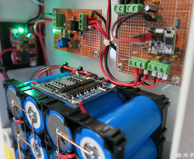
Photo of the original test prototype before PCB design.
Left green light is MPPT module showing charge complete. Center is the comparator board right is the ATtiny85 board.
-
2
-
-
5 hours ago, carlyai said:
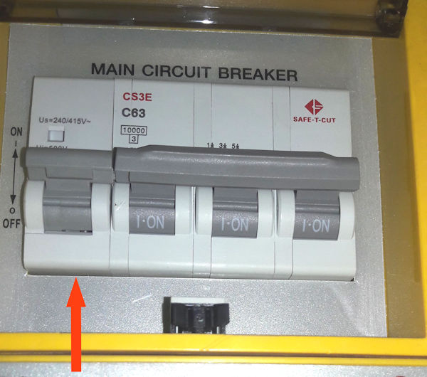
I can't find any information (except the SafetyCut pdf) on the workings of this beast.
From photo It appears Safe-T-Cut is using a standard shunt trip.
Remove cover and observe connections to the bottom of the trip.
Disconnecting one of these connections will disable the RCD.
Example shunt trip
-
1
-
 1
1
-
-
20 minutes ago, carlyai said:
Thanks for the post.
Bit difficult to change any wiring now.
If I can figure out how to stop that actuator , as Crossy suggested (if it is that causing the trouble) then changing over some breakers to RCB's would seem a good outcome.
I have a spare delay that I may be able to install in the shed CU and see if that works.
It would be nice to have an old SafetyCut 3 phase unit to work on on the bench.
Thinking, thinking.
Give the generator its own RCD and bypass the Safe-T-Cut shunt trip when transfer switch is in generator position. Maybe use transfer switch aux contacts if available or a relay.
-
1
-
-
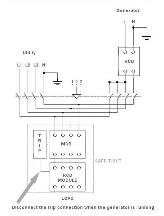
I assume there are no existing earth leaks on the load of this installation lurking just below the RCD trip level.
In theory, a three phase four pole RCD operating with all poles on the same phase should not trip if all legs are balanced, but its not always the ideal or recommended arrangement.The sensitivity level of a four pole RCD might change when all pole coils are detecting faults on the same phase.
Problems caused from four pole detection coils being in phase can be overcome by using only two poles of a four pole RCD.
When applying single phase generator power to a three phase RCD protected service it would be best to have separate earth leakage and over current protection at the generator and do the load transfer switching after the RCD's.
-
1
-
-
How does the single phase generator connect itself to the three phase service?
-
1
-
-
The body is not a good temperature indicator because humidity levels can change the way we perceive ambient temperature.
For most single room AC installations, the longer the compressor runs the greater the reduction in humidity and subsequent comfort level. If the initial ambient temperature is much higher than the set point 22/34 for example, the compressor will run for longer than if it were only 22/28.
For inverter AC's the difference between set point and actual room temperature is the error used to calculate inverter control and how quickly it reacts. An already cool room that's only one or two degrees above the set point might not dehumidify well because control has the evaporator at lower level.
In theory, undersized systems should dehumidify better than those sized correctly when set point is close to outside ambient.
-
1
-
-
24 minutes ago, SunshineHarvey7 said:
What are the specs (output volts, amps, watts)?
I have made a suggestion using your post title only and not gone into the detail. Golf cart chargers are available in the voltage and current range you desire.
Eg 48V/50A 48V/100A 60V/50A and so on...
-
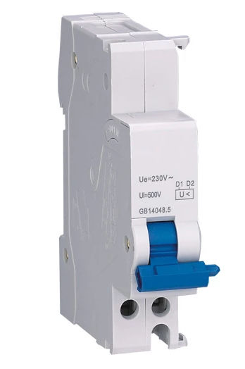
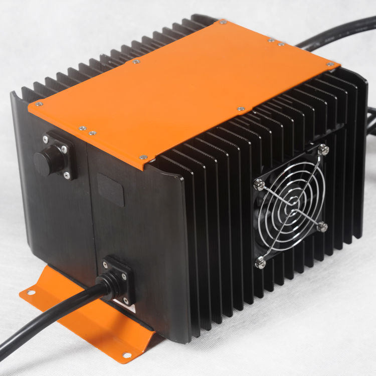
LiFePO4 golf cart charger.
-
14 minutes ago, Toolong said:
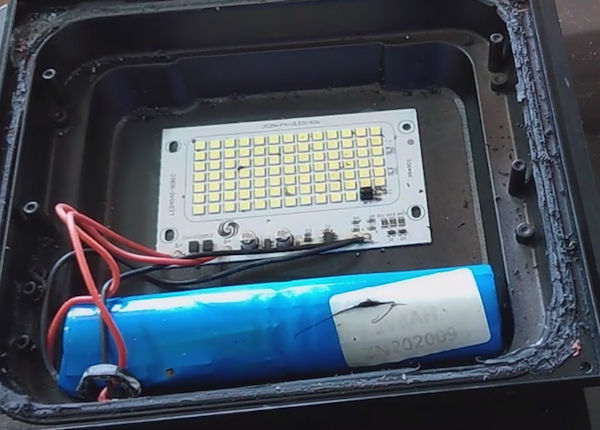
Yes, that crossed my mind. The picture Maxpower posted would allow one to see how you could do it without damaging the stuff inside.....in theory!
Gentle warming of the bonded area and a plastic spudger helps avoid breaking the glass. Not a job for the ham-fisted.
-
2
-
-
- Popular Post
- Popular Post
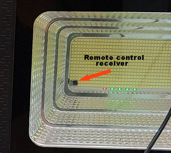
1 hour ago, Toolong said:Was not given any remote controls. (I don't know if they're required for these models....but I don't think so.)
Similar light with bonded glass forced open
-
5
-
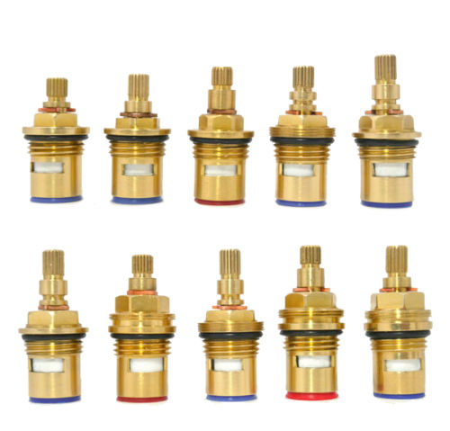
Just spotted this post.
For those preferring to repair dripping faucets.
I recently sent a parcel to my brother in LOS which included several ceramic inserts for his faucets not supported by a manufacturer.
Most faucets around Asia seem to use a standard range of 20mm-1/2 thread inserts with varying shaft lengths and direction of rotation. These are available everywhere in China so check if yours employs one of the standard inserts available at places like Shopee.
Example
-
1
-

excessive bills
in The Electrical Forum
Posted
Yes at 100% duty cycle but the PEA person in the OP's story has clearly applied what he believes to be average duty cycle and arrived at 800 Baht running cost.
In a roundabout way, this is what @KannikaP is trying to explain.